

Introduction
If you have ever spent any time in a power plant, a chemical facility, or an oil refinery, you have almost certainly seen them everywhere. Those bulbous‑shaped valves with handwheels on top, connecting pipes, controlling steam, regulating cooling water, and keeping entire processes running smoothly. They look simple enough. Turn the wheel, the stem moves, and flow changes. So what could possibly be complicated about choosing one?
Plenty, as it turns out. Not all globe valves are created equal. Some have a Z‑shaped flow path, some have a Y‑shaped path, and others turn the flow at a 90‑degree angle. Some come with bellows seals to prevent any leakage, while others are built with hardened trims to withstand abrasive media. Pick the wrong one, and you will end up with excessive pressure drop, poor control, premature wear, or—in the worst case—a valve that simply cannot do the job you need it to do. And yet, despite all these variations, the core function of a globe valve remains the same: it is a linear‑motion valve used to start, stop, and—most importantly—regulate flow. The disc moves toward or away from the seat, and as the opening changes, the valve controls exactly how much fluid passes through. But how do you know which type is right for your application? That is exactly what this guide is here to answer.
Before we dive into the selection details, let us make sure we are all on the same page about what a globe valve actually is. A globe valve is a type of linear‑motion valve where a movable plug or disc moves perpendicular to a stationary ring seat. The name comes from the originally spherical shape of the valve body, which contributed to its functionality in regulating flow. The valve body consists of two halves separated by an internal baffle, and the plug is connected to a stem that is operated by screw action or via an automated actuator. What makes globe valves special is their ability to provide fine flow control and tight valve closure, even in high‑pressure and high‑temperature environments. The disc moves perpendicular to the flow, and as you turn the handwheel, the opening between the disc and seat changes gradually, giving you precise control over the flow rate. But here is the trade‑off: that tortuous flow path creates significant resistance. The fluid has to change direction—sometimes multiple times—to get through the valve. This is why globe valves have higher pressure drops than gate or ball valves. But for applications where control matters more than raw flow, that is a price worth paying.
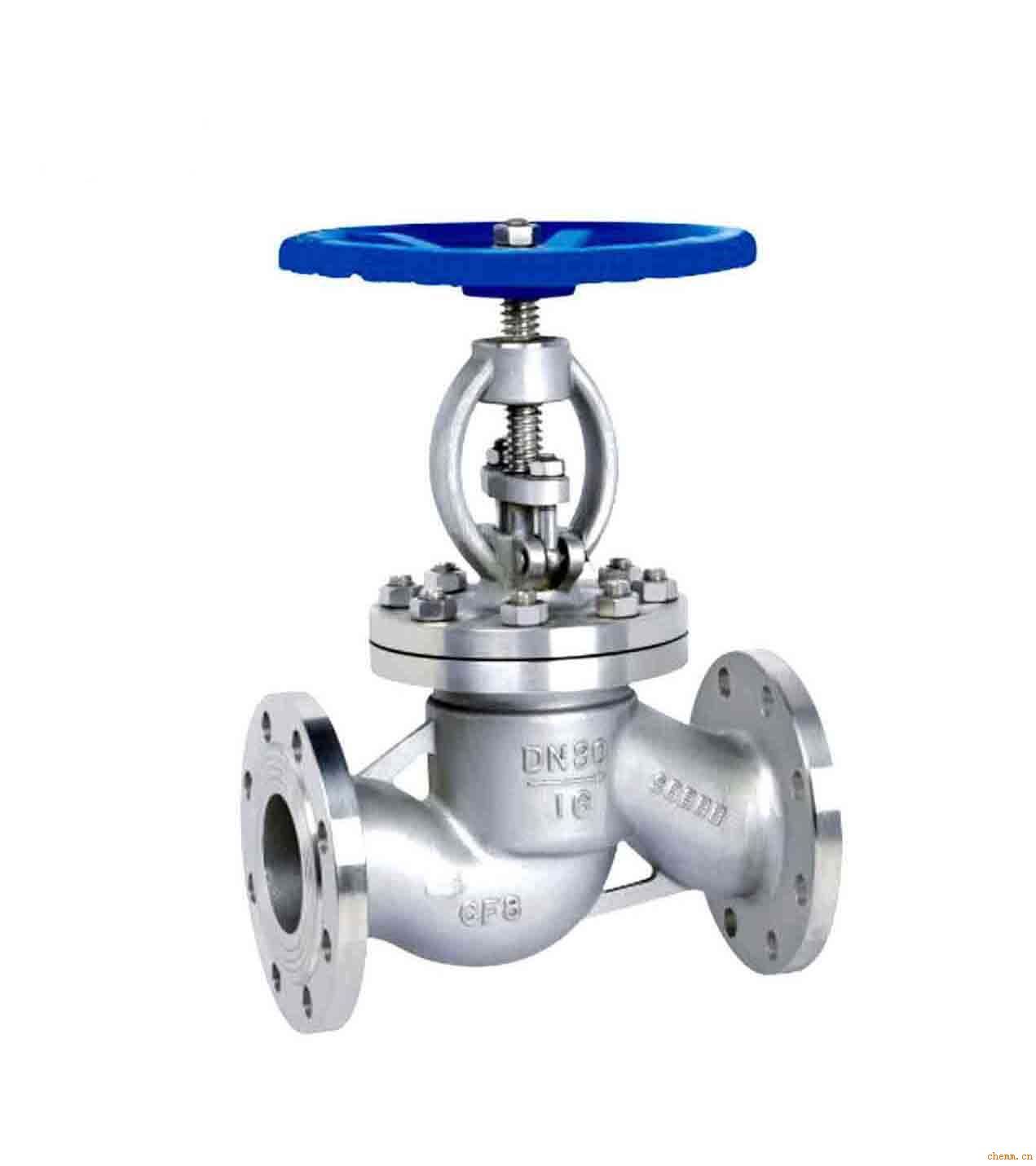
The Three Main Body Patterns: Z, Y, and Angle
When it comes to choosing the right globe valve, the very first decision you will face is the body pattern. Most industrial globe valves fall into one of three main categories: the Z‑pattern (also called tee or standard pattern), the Y‑pattern (also called oblique pattern), and the angle‑pattern. Each one is designed for a different set of operating conditions, and picking the right one is the most important step.
The Z‑pattern globe valve is the most common type you will encounter. True to its name, it is shaped like an upside‑down T, with the stem sitting at the top and the ends at opposite sides of the body. The seat is horizontal, and the disc travels perpendicular to that horizontal line. Inside a Z‑pattern valve, the fluid enters, changes direction to pass around the disc, and then changes direction again to exit. This creates a Z‑shaped or S‑shaped flow path where the fluid makes two 90‑degree turns as it travels through the valve. This type is perfect for general throttling applications where pressure drop is acceptable. You will find Z‑pattern globe valves all over the place—in bypass lines around control valves, in severe throttling services, and in any application where flow regulation is needed and pressure loss is not a major concern. However, this type has the highest pressure drop of any globe valve and the lowest coefficient of flow, so if your system is sensitive to pressure loss, you might want to consider a different pattern.
That is where the Y‑pattern globe valve comes in. Y‑pattern valves—also called oblique or wye valves—have the seat and stem angled at approximately 45 degrees to the flow. This allows for a straighter flow path when the valve is open and offers the least resistance to flow among the three main types. The Y‑pattern design reduces pressure drop by up to 50% compared to a Z‑pattern valve. The fluid does not have to make those sharp 90‑degree turns; instead, it flows through at a gentler angle, which means less turbulence and less energy loss. This makes Y‑pattern valves ideal for high‑pressure steam systems, boiler feedwater control, blow‑down and drain lines, and any application where lower pressure drop is a priority. They are often used for throttling during startup or seasonal operations, and they can be cracked open for long periods without wearing down. The only real downside is that Y‑pattern valves are generally more expensive than Z‑pattern valves of the same size because of the more complex body casting.
The third main type is the angle‑pattern globe valve, which has the two ends situated at right angles to one another—one end points straight down, and the other points out the side. Fluid flow in these valves occurs in a single 90‑degree turn. Angle valves are particularly useful when the pipeline itself needs to make a 90‑degree turn. Instead of installing a standard globe valve plus an elbow fitting, you can use an angle valve to do both jobs at once. They also handle the slugging effect that comes with pulsating flow well, so you will often see them in those sorts of applications. However, you need to be careful about installation orientation, because it can create drainage or maintenance issues if you are not mindful. Angle valves are best suited for piping systems that need a 90‑degree turn, pulsating flow applications, and installations where space is limited.
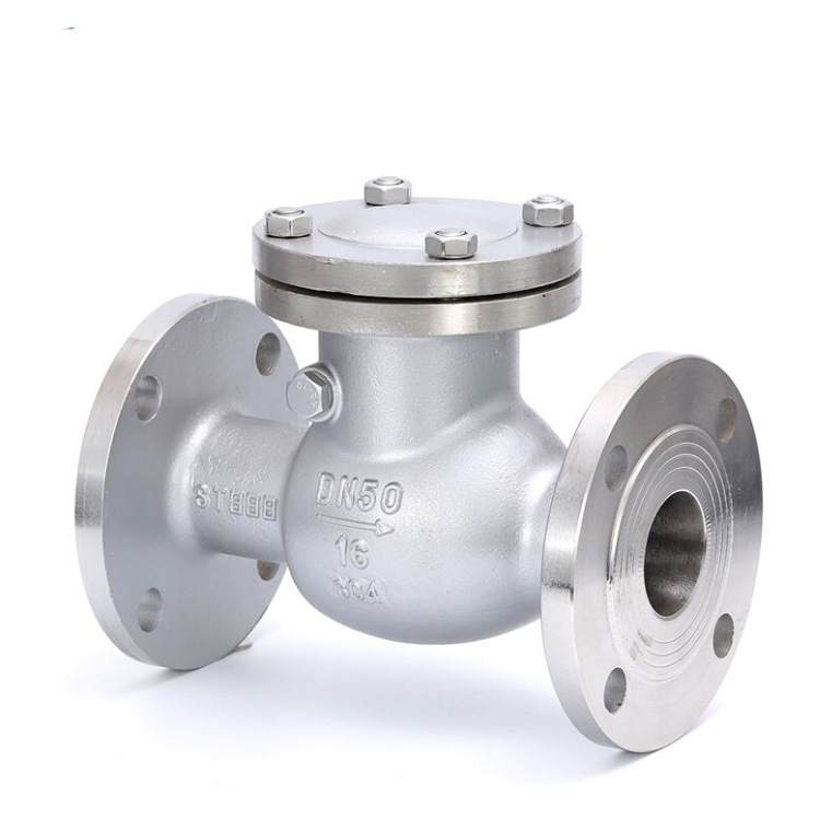
Special‑Purpose Globe Valves You Should Know About
Beyond the three main body patterns, there are several special‑purpose globe valve designs worth knowing about, because they can make a huge difference in specific services.
Three‑way globe valves have three ports and are used for mixing or diverting flow. Instead of just controlling flow in a single line, they can combine two incoming streams into one outgoing stream, or split one incoming stream into two outgoing streams. These are commonly used in temperature blending and flow mixing applications, where you need to adjust the proportion of hot and cold fluids, for example.
Bellows‑sealed globe valves replace the traditional packing with a welded metal bellows that surrounds the stem, providing a zero‑leakage seal. This is absolutely critical for toxic gases, hazardous fluids, vacuum systems, and any service where fugitive emissions must be prevented. You will find them in nuclear power plants, aerospace facilities, pharmaceutical manufacturing, and chemical processing plants handling aggressive chemicals. They cost more, but when safety and environmental regulations are strict, they are non‑negotiable.
And then there are needle valves, which are essentially a specialized globe valve with a fine‑tapered, needle‑like disc. The needle fits into a matching seat, and as you turn the handle, it moves in and out of the seat, providing extremely fine flow control. These are perfect for instrumentation systems, sampling lines, dosing and metering applications, and any situation where you need to control very small flows with high precision. They are typically available in smaller sizes, from ¼ inch up to about 1 inch, and are a staple in analytical and laboratory settings.
How to Choose the Right Globe Valve – Step by Step
Now that you know the different types, how do you actually make a decision? The selection process can be broken down into a logical sequence of steps, and if you follow them, you will avoid most of the common pitfalls.
First, determine your primary function. Are you using this valve for on/off isolation, or for throttling and flow regulation? If you just need to turn flow on and off, a gate valve or ball valve might be a better and cheaper choice. Globe valves are designed for throttling and regulation, so if you are going to be adjusting flow frequently or maintaining a specific flow rate, a globe valve is the right tool for the job. If you only close it once a month, maybe think twice.
Second, evaluate your pressure drop tolerance. This is where the body pattern decision really matters. If pressure drop is not a major concern, choose a Z‑pattern globe valve—it is the most common, most available, and usually the most affordable. If you need to minimize pressure drop because your pump is already struggling or your system is energy‑sensitive, choose a Y‑pattern valve. If your piping layout naturally needs a 90‑degree turn, choose an angle‑pattern valve, because it eliminates the need for a separate elbow fitting and reduces overall pressure loss.
Third, consider your media. What are you actually flowing through the valve? For steam, globe valves are the industry standard because they can handle high temperatures and pressures while providing precise control. Y‑pattern valves are often preferred for high‑pressure steam systems because of the lower pressure drop. For clean liquids and gases, any of the three main patterns will work—just choose based on pressure drop and piping layout. For corrosive or hazardous fluids, a bellows‑sealed globe valve is a wise choice to prevent stem leakage. For slurries or fluids with solids, globe valves are generally not recommended because the tortuous flow path can cause clogging and erosion; you would be better off with a knife gate valve or a ball valve in those cases.
Fourth, check temperature and pressure ratings. Globe valves are available in pressure classes from Class 150 all the way up to Class 2500, but the pressure rating drops as temperature goes up. A Class 150 flange might be rated for 285 psi at room temperature, but at 400°F, that rating drops significantly. Always check the pressure‑temperature chart for the specific material and design you are considering. Do not assume that “Class 150″ means “150 psi” at your operating temperature—that is a common and dangerous mistake.
Fifth, size the valve properly. Oversizing is one of the most common—and most costly—mistakes in valve selection. A valve that is too large for the application will not provide good control. The flow will be unstable, and you will struggle to make precise adjustments because the valve will be operating at a very small percentage of its full opening. Calculate the required flow coefficient (Cv) from your flow rate, fluid density, and allowable pressure drop, then match it to a valve size. If you are not sure how to do this, consult with a valve specialist who can help you with the calculations—it is well worth the time.
Sixth, consider automation. Will this valve be operated manually, or will it be automated? If you are planning to use an electric or pneumatic actuator, you need to consider the torque or thrust requirements. Globe valves require higher thrust than quarter‑turn valves like ball valves, and they typically need linear actuators with positioners for precise control. This adds cost and complexity, so make sure you factor that into your budget and control system design.
Finally, do not forget the flow direction. Globe valves are unidirectional. Every globe valve body has an arrow indicating the required flow direction. Install it backward, and you will experience poor sealing, increased operating torque, and premature failure. The standard flow direction for most globe valves is “low inlet, high outlet”—fluid enters from the underside of the disc and exits from the top. But always check the arrow on the specific valve you are installing, because some special designs may have different requirements.
Common Mistakes That Cost You Money
Even experienced engineers make certain mistakes over and over again, and they can be expensive. Let me share the most frequent ones so you can avoid them.
The first and perhaps most common error is oversizing the valve. As I mentioned earlier, a valve that is too big will never give you good control. You will find yourself trying to make tiny adjustments that cause big flow jumps, and the valve will spend most of its time nearly closed, which also accelerates wear on the seat and disc. Always size for the actual operating range, not the maximum pipe size.
The second mistake is ignoring pressure drop entirely. Many engineers select a globe valve just because it is a globe valve, without calculating how much pressure they will lose across it. Then they wonder why their pump discharge pressure is insufficient or why the system doesn’t perform as designed. Always include the valve’s pressure drop in your hydraulic calculations.
The third mistake is choosing the wrong body pattern for the application. Using a Z‑pattern valve when you need low pressure drop, or using a Y‑pattern valve when a Z‑pattern would work fine—these are common errors that cost you either in performance or in unnecessary expense. Match the pattern to the application, not to habit.
The fourth mistake is ignoring material compatibility. A valve that works perfectly with water may fail quickly with corrosive chemicals or high‑temperature steam. Always check the manufacturer’s chemical compatibility charts, and remember that trim materials—the disc, seat, and stem—are just as important as the body material. Sometimes you can save money by choosing a carbon steel body with stainless steel trim, while in other cases you need full alloy construction.
The fifth mistake is installing the valve backward. It sounds too basic to be a real problem, but it happens more often than you would think. The flow arrow is there for a reason. If you ignore it, you will not only get poor sealing but also risk damaging the valve internals because the pressure acts on the wrong side of the disc.
The sixth mistake is specifying the wrong seat leakage class. Different applications require different levels of shut‑off tightness. If you need bubble‑tight shut‑off, you need a soft‑seated globe valve or a specially lapped metal‑seated valve. A standard metal‑seated globe valve will not give you zero leakage, and if you expect it to, you will be disappointed. Always define your leakage requirement clearly when ordering.
When to Use Globe Valves – and When Not To
Let me be clear: globe valves are excellent valves. They are just not the right choice for every single application. Use globe valves when you need to regulate or throttle flow, when you need precise and repeatable control, when the application involves steam, high temperatures, or high pressures, when you can accept some pressure drop in exchange for control, and when the valve will spend significant time in a partially open position. On the other hand, do not use globe valves when you just need on/off isolation—use a gate or ball valve instead—when pressure drop must be absolutely minimized, when the media is viscous or contains solids, when you need bidirectional flow, or when the pipeline is very large (globe valves are typically used up to about 24 inches, and beyond that, other types are more practical).
Conclusion
The globe valve has been around for over 200 years, and it is not going anywhere. Its ability to provide precise flow control makes it indispensable in countless industrial applications. But choosing the right one requires more than just picking a size and a pressure class. You need to consider the body pattern, the trim materials, the flow direction, the pressure drop, and the specific demands of your application. A Z‑pattern globe valve is the workhorse—good for most general throttling. A Y‑pattern valve gives you lower pressure drop when you need it. An angle valve saves space and handles direction changes. A bellows‑sealed valve prevents leakage in hazardous services. A needle valve gives you precision at low flows. The key is to match the valve to the job, not to guess or to go with whatever is cheapest or most familiar. Take the time to evaluate your system, calculate your requirements, and consult with specialists if needed. Because in the end, the best valve isn’t the most expensive one or the cheapest one—it is the one that does exactly what you need it to do, reliably and cost‑effectively, for years to come.
Post time: Aug-21-2026